Journal Name: Scholar Journal of Applied Sciences and Research
Article Type: Research
Received date: 29 August, 2018
Accepted date: 12 September, 2018
Published date: 20 September, 2018
Citation: Yousufuddin S (2018) Heat Transfer Enhancement of a Shell and Tube Heat Exchanger with Different Baffle Spacing Arrangements. Sch J Appl Sci Res. Vol: 1, Issu: 6 (50-56).
Copyright: © 2018 Yousufuddin S. This is an open-access article distributed under the terms of the Creative Commons Attribution License, which permits unrestricted use, distribution, and reproduction in any medium, provided the original author and source are credited.
Abstract
For the purpose of heat transfer enhancement, the configuration of a shell-and tube heat exchanger was improved by considering the baffle spacing and baffle cut. The investigation in this paper was carried by manual calculations, and that performed for a single shell and two tubes passes heat exchanger, with variable number of baffles spacing and 25% baffle cut. Designed baffle spaces are: for case A: 382 mm, for case B: 427 mm, for case C: 472 mm, and for case D: 517 mm. In our paper we obtained shell side calculations using Kern method and the results were observed on shell side, the heat transfer coefficient decreases by 15.3% and pressure losses decreases by 49.4%. General design considerations and design procedure that follows TEMA standard are also considered in this paper. Also, commercial HTRI Exchanger Suite software was also used for design drawing purposes.
Keywords
Shell and tube heat exchangers, Optimization, Design, Baffles.
Keywords

Introduction
In most industrial fields, cooling and heating fluids are needed. The device utilized to implement the heat transfer between the fluids is termed as heat exchanger. In most heat exchangers, the fluids are separated by a heat transfer surface, and ideally they do not mix. It is used in many applications such as space heating and airconditioning, power production, waste heat recovery, and chemical processing [1-2]. Commonly, they are classified according to transfer process, flow arrangements, heat transfer mechanisms, construction, and degrees of surface compactness, pass arrangements, and phase of the process fluids [3].
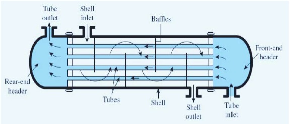
The most common type of heat exchangers utilized in industrial fields is the shell and tube heat exchanger according to their low costs, structural simplicity, and design flexibility [2]. The shell and tube heat exchanger is classified according to construction [3]. This type of heat exchanger is good mechanical layout and good for pressurized operation. It is made up of different type of materials in which selected materials is used for operating pressure and temperature [4]. It has many applications in the power generation, petroleum refinery, chemical industries, and process industries. They are used as oil cooler, condenser, feed water heater, etc. [3]. The shell and tube heat exchangers since they were designed and manufactured, they are having problems affecting the performance of the exchangers. The main common problem is fouling. This problem is highly considered by engineers. Fouling is an aggregation of undesirable material on heat exchanger surfaces which decreases heat transfer rate and increasing the resistance to fluid flow, resulting high pressure drop [3] (Figure 1).
Figure 1: Shell and tube heat exchanger basic components.
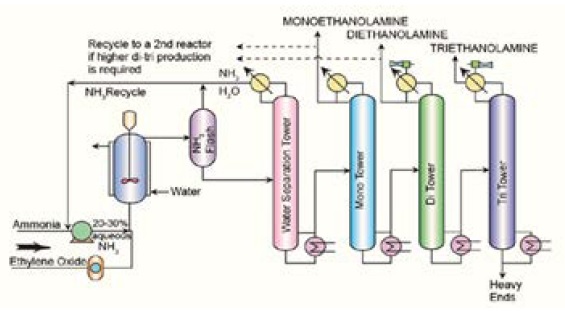
The principal components of a shell and tube heat exchanger are shell, shell cover, tubes, channel, channel cover, tube sheet, nozzles, and baffles as shown in Figure 2 [3]. The main component on which this article is focusing is the baffles. Baffles are plates installed in the shell side used to support the tubes, maintain the spaces between the tubes, and direct the shell side fluid flow across or along the tube bundle in a specified manner [3]. Segmental baffles are the most commonly used. They improve the heat transfer by enhancing fluid turbulence or local mixing on the shell side as a result of causing the shell side fluid to flow in a zigzag manner across the tube bundle. It also increases the pressure drop. As a result, it requires high pumping power, so it increases the electricity consumption [5]. We have studied and tested the effects of the central distance between the baffles for four different designs. We’ve seen that the different baffles spacing enhance the heat transfer rate which is considered as one of the most common problems occurs in this device. Our study has application of producing diethanolamine and triethanolamine. In the production process as shown in Figure 1, after each distillation tower there is a shell and tube heat exchanger.
Figure 2: Flow sheet production of ethanolamines.
Design Methodology
Heat transfer mode in a shell-and-tube heat exchanger usually involves convection in each fluid and conduction through the wall separating the two fluids. In the analysis of shell-and-tube heat exchangers, it is convenient to work with an overall heat transfer coefficient U that accounts for the contribution of all these modes at heat transfer. The rate of heat transfer between the two fluids at a location in a heat exchanger depends on the magnitude of the temperature difference at that location, which varies along the shell-andtube heat exchanger [6,7].
Therefore, in the heat transfer analysis of heat exchangers, it is convenient to establish an appropriate mean value of the temperature difference between the hot and cold fluids such that the total heat transfer rate between the fluids, and that can be determined from [8].
Where:
A is the total hot-side or cold-side heat transfer area.
U is the average overall heat transfer coefficient based on that area.
LMTD (Log Mean Temperature Difference) method is very suitable for determining the size of a heat exchanger to realize prescribed outlet temperatures, when the mass flow rates, the inlet, and outlet temperatures of the hot and cold fluids are specified [8].
Where:
ΔT1=Th,1-Tc,2
ΔT2=Th,2-Tc,1
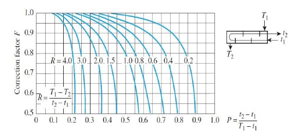
For multipass and cross-flow heat exchangers, the log mean temperature difference should be corrected using a correction factor (F). F is nondimensional, it depends on the temperature effectiveness P, the heat capacity rate ratio R, and the flow arrangement.
Where:
The correction factors for a shell-and-tube heat exchanger with one shell and two tube passes are presented in Figure 3.
Figure 3: LMTD correction factor F for a shell-and-tube heat exchanger with one shell pass and two or a multiple of two tubes passes.
The convective heat transfer coefficient h is dependent upon the physical properties of the fluid and the physical situation. For tube side the convective heat transfer coefficient hi can be calculated by (5). For shell side the convection heat transfer coefficient hₒ can be determined using Kern method (6).
The overall heat transfer coefficient represents the total resistance to heat transfer from one fluid to another, and it’s influenced by the thickness and thermal conductivity of the mediums through which heat is transferred. The larger the coefficient, the easier heat is transferred from its source to the product being heated. It is classified in two part [8].
• The overall heat transfer coefficient for clean surface
• The overall heat transfer coefficient for fouled surface
Where Rf,total is the total fouling resistance, given as
The designer simply adds a certain percentage of clean surface area to account for fouling. The added surface implicitly fixes the total fouling resistance depending upon the clean surface overall heat transfer coefficient. The overdesign percentage should not be more than about 30% (10). Also, cleanliness factor an important term cleanliness factor is a term relates the overall heat transfer coefficient when the heat exchanger is fouled to when it is clean. This approach provides a fouling allowance that varies directly with the clean surface overall heat transfer coefficient (11) [9].
So, the heat transfer rate of a counter flow arrangement can be obtained from (12).
As a fluid flows through a heat exchanger there will normally be a pressure drop in the direction of the flow (in some special situations where the fluid velocity decreases, there may be an increase in pressure). Pressure drops occur in the flow channels, nozzles, manifolds, and truing regions in the headers of heat exchangers and each of these pressure drops must be evaluated, unless experience suggests that one or more may be neglected [10].
The tube-side pressure drop can be calculated from (13).
The change of direction in the passes introduces an additional pressure drop ΔPr, and that can be obtained using (14).
So, the total pressure drop of tube-side becomes:
The shell-side pressure drop depends on the number of tubes the fluid passes through the tube bundle, between the baffles as well as the length of each crossing [8].
Determining baffle spacing and baffle cut
Baffle spacing is the centerline-to-centerline distance between adjacent baffles and identified as the most important geometric parameter affecting both pressure drop and heat transfer characteristics on the shell side design. It affects the velocity of the shell side fluid which thereby affects the heat transfer, the smaller baffle spacing, the smaller flow area, and the higher the fluid velocity. This increment in the fluid velocity represents an increase in the frictional pressure drop and the heat transfer coefficient. Although, reducing the baffle spacing increase the heat transfer coefficient, there is a lower limitation for it set by the TEMA Standards, of one-fifth the shell diameter and never less than 2 in (51 mm). If the baffle spacing is higher, the heat transfer coefficient is decreased. In addition, higher baffle spacing lead to longitudinal flow which is less efficient than cross flow and large unsupported tube spans which will make the heat exchanger prone to tube failure due to flow-induced vibration. Also the maximum baffle spacing is specified by the TEMA standards by mechanical considerations. This is because the purpose of the baffle in addition to improve the heat transfer coefficient is to support the tubes also.
The heat exchanger designer has to select a baffle spacing to perform the maximum possible value of the heat transfer coefficient without exceeding the allowable pressure drop of the shell side fluid. The baffle cut is expressed as a percentage of the shell inside diameter which varies between 15% and 45%. The most common baffle cut is about 25%. Both very small and very large baffle cuts are detrimental to heat transfer due to the deviation from an ideal situation. For low baffle cut, the shell side fluid turbulence is high and hence the fluid velocity at the window is high. As a result, the heat transfer coefficient increases. However, for large baffle cut, there will be important zones of the fluid with low velocities and hence low heat transfer coefficients. Reducing the baffle cut below 20% in order to increase the heat transfer coefficient or increasing it beyond 35% in order to decrease the pressure drop usually lead to poor design. In order to achieve that, the designer should change the aspects of tube bundle geometry instead of reducing the baffle cut below 20% or increasing it beyond 35% [10]. The effects of the baffle cuts in the shell side fluid streamlines corresponding to different baffle cuts. Optimum baffle spacing is somewhere between 0.4 and 0.6 of the shell inside diameter and a baffle cut of 25% to 35% is usually recommended.
Results and Discussion
The Tables 1 and 2 shows the available design data and properties of both tube side and shell side fluid.
Table 1: Available design data.

Table 2: Properties of Water and Lean DEA at an average temperature.

Table 3 depicts the constant values used for analytical calculation for tube side and whereas the Table 4 shows the summary results of a shell side calculation for different baffle spacing for the different designs namely A, B, C and D considered in this research work.
Table 3: Constant values of tube side and some properties of both fluids.
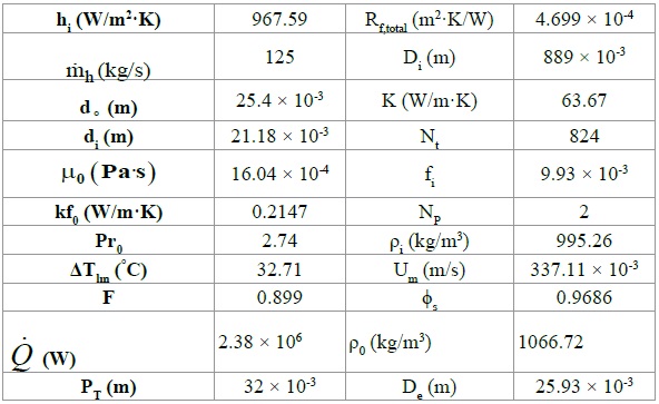
Table 4: Summary results of different designs due to varying baffle spacing.
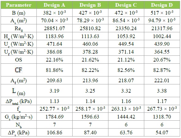
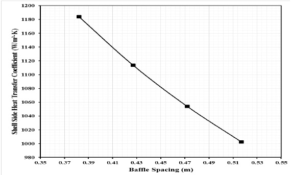
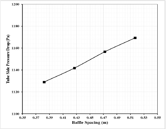
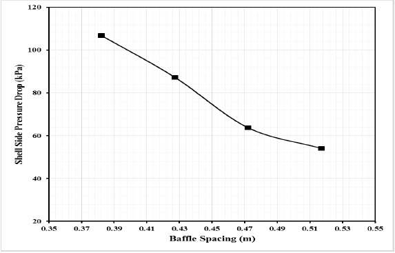
From the summarized results as shown in Table 4 we compared the shell side heat transfer coefficient and total pressure on the tube and shell side with various baffle spacings, which are depicted in Figures 4-6 respectively.
Figure 4: Shell side heat transfer coefficient vs. baffle spacing.
Figure 5: Tube side pressure drop VS baffle spacing.
Figure 6: Shell side pressure drop vs. baffle spacing.
Figure 4 shows the effects of baffle spacing on shell side heat transfer coefficient, where the maximum and minimum values of shell side heat transfer coefficient are 1183.96 and 1002.44 W/m2·K, respectively. It’s clear, with increasing baffle spacing the heat transfer coefficient decreases, and that because increasing central baffle distance means changing flow type. The percentage decrease in the Reynolds number between design A and D is 26.1% in the turbulent region, and that percentage quite enough to change flow type. Therefore, this results in a decrease in heat transfer, and from fluid mechanics we know that the high turbulent fluid flow results in high heat transfer.
Figure 5 shows the effects of baffle spacing on tube side pressure drop, where the maximum and minimum values of tube side pressure drop are 1169.35 and 1129.05 Pa, respectively. We notice, with increasing central baffle distance the pressure drop increases, and that because increasing baffle spacing means increase in tube length. The result shows that with increasing tube length the tube side pressure drop increases by 3.7%. That means changing of baffle spacing will not make much impact in tube side pressure drop.
Figure 6 shows the effect of baffle spacing on shell side pressure drop, where the maximum and minimum values of shell side pressure drop are 106.86 and 54.07 kPa, respectively. The graph demonstrates with increasing baffle spacing the shell side pressure drop decreases, and that is due to shell fluid mass velocity. The increasing in central baffle distance results decreasing in shell fluid mass velocity by 26.1%, and this percentage is enough to decrease shell side pressure drop by 50%.
Design Simulation by HTRI software
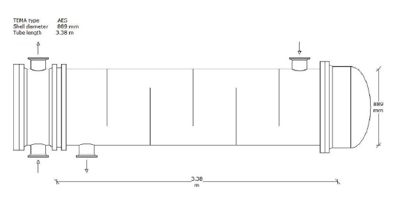
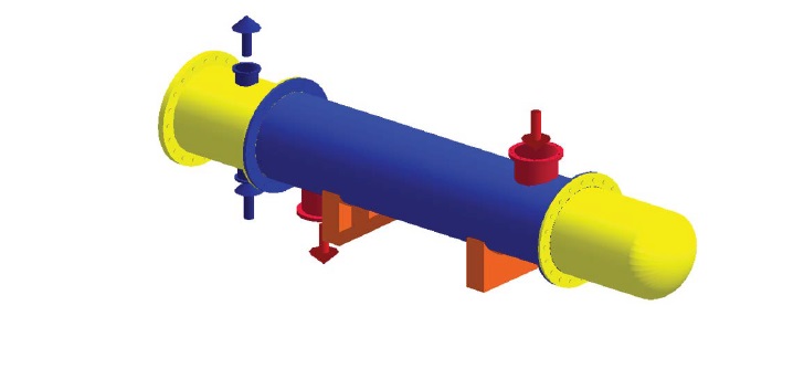
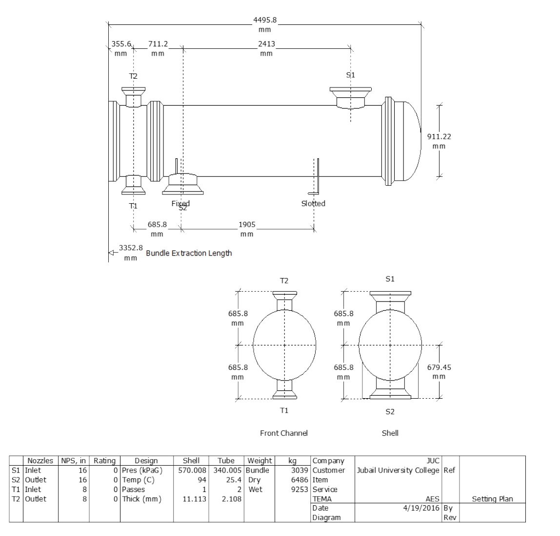
In this work, we used HTRI software to simulate the drawing for best design. Figure 7 shows design side view. We notice the number of baffles by HRTI software is 5 based on design D, where the number of baffles according to our manual calculations is 6 (Table 4). The Figure 8 shows the 3-D view of the best design D obtained and Figure 9 gives the total length of 4495.8 mm (as per TEMA standards) for a shell and tube heat exchanger.
Figure 7: Side view of shell and tube heat exchanger design D.
Figure 8: 3-D view of shell and tube heat exchanger design D.
Figure 9: Setting plan of shell and tube heat exchanger design D.
Conclusion
In this paper we presented a detail design of a shell and tube heat exchanger for cooling Lean Diethanolamine, which is considered as an important fluid in petrochemical plants especially for environmental purposes. The effects of changing single segmental baffle spacing of the exchanger on heat transfer and pressure drop have been studied. Therefore, we considered four designs that follows TEMA standard and we simulated the best design according to heat transfer and pressure drop factors. From the results we noticed that between designs A and D the heat transfer coefficient of shell side decreases by 15.3%, the tube side pressure drop increases by 3.7%, and pressure drop of shell side decrease by 49.4%.
Acknowledgment
The authors express their sense of gratitude to Jubail University College, KSA for the support extended in the utilization of the facilities for conducting the research work.
There is no references
