Journal Name: Scholar Journal of Applied Sciences and Research
Article Type: Research
Received date: 09 September, 2018
Accepted date: 04 October, 2018
Published date: 11 October, 2018
Citation: Palaniappan V (2018) Nonlinear Aerodynamic Analysis of Low Aspect Ratio Wings with Control Surfaces . Sch J Appl Sci Res. Vol: 1, Issu: 7 (33-38).
Copyright: © 2018 Palaniappan V. This is an open-access article distributed under the terms of the Creative Commons Attribution License, which permits unrestricted use, distribution, and reproduction in any medium, provided the original author and source are credited.
Abstract
This paper introduces and develops a nonlinear theory that extends the linear Prandtl Lifting Line theory. Lifting Line theory works well for wings with large aspect ratios, but fails for wings with small aspect ratios. In the context of Micro Aerial Vehicles (MAVs), the size constraints impose a need for wings and control surfaces with small aspect ratios. Hence, a nonlinear theory is introduced in this paper. The theory uses a system of vortices with variable strength, and using the boundary conditions, solves for vortex strength. Using that, we are able to find the lift generated by the given surface. I extend this by considering control surfaces where the angle of attack is changed and investigate the response of lift. This response is then compared with response of general aircraft airfoils.
Keywords
Aerodynamics, Lifting line theory, Prandtl’s theory, Nonlinear.
Introduction
The intend of this paper is to develop a nonlinear theory that extends the classical Prandtl Lifting Line theory. Over the years, there has been minimal research into theoretical methods to find the aerodynamic characteristics of wings that have low aspect ratio, especially when the Prandtl theory does not provide accurate predictions. This is especially applicable to the research and development of Micro Aerial Vehicles (MAVs) due to their small size and inability to have wings with large aspect ratios [1,2]. Furthermore, when considering control surfaces on the MAVs, the aspect ratio is definitely limited to low values, to maintain size and stealth. However, it is also necessary for MAVs to have manoeuvrability to navigate urban environments and gain intelligence. Hence, the following nonlinear theory is used for the investigation of the response of the coefficient of lift to flap deflections.
Materials and Methods
I have used a similar approach to the nonlinear theory as Bollay [3], and have reached the same results, confirmed by the approach to Prandtl’s Lifting Line Theory [4] for large aspect ratios.
Assumptions
Let us use a flat rectangular plate for our analysis. The plate will have span of b and chord c, at an angle of attack of α, with free stream velocity V. So, the component of free stream velocity tangent to the wing is Vsin(α) and normal to the wing is Vcos(α). For our analysis, we are going to replace the wing with a system of bound and trailing vortices, and use the induced velocities to satisfy the boundary condition of no flow through the wing, to find the strengths of the vortices. Therefore, we make the following assumptions:
- The vortex strength across the span of the wing.
- The downwash is constant across the span and equal to the value at the centre of the span.
Biot-Savart law
We will be using the Biot-Savart law [5] to find the induced velocities by the the vortices:
Induced velocity by bound vortices
Now we will find the induces velocities due to the hound vortices.
We need to integrate this with respect to from to , so it becomes:
As for the boundary condition, the when z is slightly above zero and when z is slightly below zero.
Now, we can use the following transformation to dimensionless coordinates:
Where γ is the aspect ratio.
Now the induced velocities due to bound vortices in terms of the new coordinates equals:
Induced velocities by trailing velocities
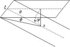
Now we will investigate the induced velocities due to the trailing vortices. Consider the Figure 1.
Figure 1: Trailing vortex geometry.
From it we can derive the following relations:
Also, from Biot-Savart Law, we know that
Furthermore, from the geometry of the wing, we can deduce that
Now, combining the above information, we obtain the following:
Now, as with the bound vortices, we transform the coordinates into non-dimensional coordinates, and we obtain:
Now we are in position to formulate the integral equation to solve for
The integral equation
As we discussed in Assumptions, we will use the induced velocities to satisfy the boundary conditions, and hence derive the vorticity strength . However, since we are only concerned in calculating the total normal force and hence the lift coefficient, we will only consider the vortex strength at the mean span, since our assumption allows such an approach. So the integral equation for the boundary condition becomes
Note that we have used the dimensionless coordinates. Now expanding fully and switching the x and integrals, we get
Where
The integrals Σ1, Σ2 and Σ3 can be evaluated by the substitutions , and respectively. Consequently, the results are as follows:
Now we shall assume a reasonable vortex strength distribution over the wing, of the form , and proceed to integrate the expressions:
Now, rearranging the terms, we can evaluate the constant to obtain the following expression:
Having integrated the integrals, the final results of that analysis is as follows:
Where
Note that l1 refers to the modified Bessel Function of first order [6].
Results and Discussion
Finding the tangent velocity induced across wing
In the linear wing theory, the angle of attack is assumed to small enough that the tangential velocity induced by the vortices is negligible. However, in our nonlinear theory, the velocity induced by the vortices must be taken into account in order to calculate the lift generated by the wing. So, to find the induced tangential velocity, we need to consider the velocity induced by both the bound vortex and he trailing vortex. For the bound vortex, the velocity induced at the opposite wing tips cancel out to give zero at the mean, which is what we are concerned with. For the trailing vortex, there is a induced velocity component along the wing equal to
However, we are only concerned with the mean value of the velocity as we are going to use it to find the lift generated. The mean velocity is therefore
From our analysis before, we can rewrite the equation above into
Finding the angle of trailing vortex
According to Helmholtz Vortex Law, the vortex follows the path of the fluid particles [7], and so, the angle of the trailing vortex is the same as the angle of resultant velocity vector. However, due to the size and Reynolds number, there will be inherent instabilities in the flow after the wing [8]. Therefore, we can make the approximation that the angle of the vortex right after the trailing edge will suffice for our analysis. The angle of the vortex as it leaves the trailing edge can be calcuated as follows. We first need to determine the mean velocities of the induced velocities. This is done by considering a wing of span that is twice the span of our current wing. It is trivial to see that due to the fact that only the opposite vortex sheet can induce a velocity at the mean value. Therefore, the mean velocities are as follows:
So the resultant velocity vector can be determined as such:
This is an implicit equation of 𝜃 and can only be solved numerically.
Calculating the lift force
In the linear lifting line theory, we were able to calculate lift using the Joukowsky-Kutta Theorem, due to the small angles of attack assumed. However, for our nonlinear analysis, we need to account for the tangential flow across the wing to calculate the lift accurately. Therefore the overall lift becomes:
I have omitted the details of the manipulation for the sake of clarity. Therefore, after long analysis, the coefficient of lift is
Limiting case of
When the aspect ratio tends to infinity, the various terms in the lift coefficient take the following values:
Clearly, this agrees with Prandtl’s Lifting Line Theory.
Limiting case of γ=0
For the case of zero aspect ratio, the components of the formula reduce to the following values:
Therefore, the lift force now becomes
This is a very interesting result, and it corresponds to the solution using momentum theory applied to Newtonian flat plate, where the induced force due to momentum change of the particles is
Using nonlinear theory for flap deflections
Flap configuration: Given the flap configuration in Figure 2, we shall approximate the overall lift to be
Figure 2: Flap configuration.
Calculation of overall lift coefficient: We know from our nonlinear analysis that are the only functions dependent on the angle of attack. So letting the angle of attack of the flap be , we obtain the overall lift coefficient:
We shall define the flag chord ratio as . The total lift coefficient becomes
Computation of
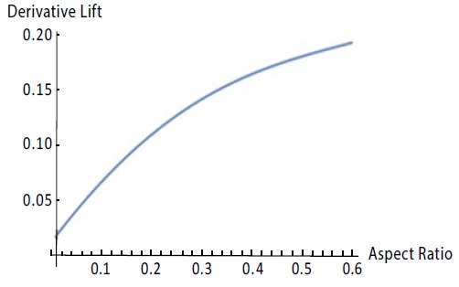
The only term that contributes to the aerodynamic derivative is . Hence, to compute the aerodynamic derivative, we need to find . This was done using Mathematica, and the results are in Figure 3.
Figure 3: CLflap ′ vs Aspect ratio.
Comparing with wings of different high aspect ratio
Since for MAVs, we cannot effectively have a tail with elevators [9,10], due to the downwash effect and lack of size to design in a way that avoids the downwash from the wing, we are forced to use the ailerons and flaps for both lateral and longitudinal control. Hence, it is important to compare with our results. We get values for as 5.70, which is much bigger than our results for low aspect ratio wings [11]. It can be inferred that due to this, the deflections required by the low aspect ratio wings and control surfaces will be much greater and elicit much different control systems to implement such deflections. An issue would be the behaviour of the control surfaces at high angles of attack, but that is beyond the scope of this research.
Conclusion
Overall, we have used the nonlinear modified version of Prandtl’s Lifting Line Theory to derive the lift coefficient of low aspect ratio wings. The results concur with classical lifting line theory for high aspect ratios. Furthermore, this method is useful in designing control surfaces such as flaps for MAVs due to their size restriction [12].
There is no references


