Journal Name: Scholar Journal of Applied Sciences and Research
Article Type: Research
Received date: 18 May, 2018
Accepted date: 14 June, 2018
Published date: 21 June, 2018
Citation: Meziane A, Cherfia A (2018) Study of the Working Space of A Constrain Parallel Robot Reconfigurable of Three Degres of Freedom (3 DOF). Sch J Appl Sci Res. Vol: 1, Issu: 3 (81 - 86).
Copyright: © 2018 Meziane A. This is an open-access article distributed under the terms of the Creative Commons Attribution License, which permits unrestricted use, distribution, and reproduction in any medium, provided the original author and source are credited.
Abstract
The determination of the workspace is a very important aspect from the design of a robot in order to specify its margins of maneuver and to define all the points reachable during its operation. In this article, we present the study of the geometric reconfigurations of a constrained robot with three degrees of freedom (D.O.F), which are obtained by adjusting the length of the three kinematic chains and which lead us to plot the working spaces of the robot. To do this, we propose a method allowing to obtain a 3D representation of the workspace. This method is exact in the sense that it allows to determine the geometric nature of the boundary of the workspace. We do not therefore use a discretization of the translation parameters.
Keywords
Parallel robot, Constrain parallel robot, Reconfigurable robot, Workspace.
Introduction
Parallel architectures appeared about 50 years ago with the Stewart-Gough rig and the first flight simulators. They have since been used in other applications requiring more precision, robustness, stiffness and the ability to handle heavy objects with large accelerations or assembly in applications that require high accuracy and control of contact efforts. . The concept was recently adopted in the field of the machine tool for high speed machining applications [1].
Reconfigurable robots are intelligent systems that can autonomously change their configuration to accommodate changing environments and tasks. The notion of reconfiguration is used in areas as different as the automatic, the electronics, the computer, the communications or the manufacturing systems of production [2]. The main idea of developing reconfigurable systems is based on the use of modular components [3].
The interest in research and development in modular robotics is guided by the need to find a balance between cost and the ability to be multitasking, while improving the effectiveness of action.
Selvakumar and Kumar [4] Offer a modular threesegment parallel robot. Each segment contains four modules where there are two actuator modules, one module which constitutes a passive cylindrical seal and a module connected to the end of the segment and containing a passive spherical joint. Mayaet al. [5] have taken over the well-known Delta robot structure, which consists of three closed-loop kinematic chains and proposed a new reconfigurable structure by symmetrically adjusting the length of the kinematic chains. The determination of the working space is more complex than for the series manipulators, because of the coupling between the translations and the orientations.
In this article, we propose a method to obtain a 3D representation of the workspace for a given orientation.
Description of the Mechanical System
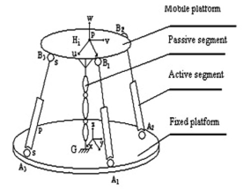
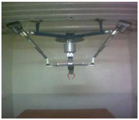
The parallel robot studied is a manipulator 3ddl (degrees of freedom) which consists of a fixed base and a mobile platform interconnected by three active segments (motorized) and a passive central segment [6] (Figures 1 and 2).
Figure 1: prototype diagram.
Figure 2: Photo of four-segment constrained parallel robot.
The three active bars are connected to the movable base by three d.d.l ball joint connections and to the fixed base by two d.d.l universal joints; the three d.d.l passive central bar may have several configurations or types of mechanical structures, but we choose a PPP type structure to give the manipulator a pure translation [7-10].
General Method of Obtaining the Reverse Geometric Model
To determine the inverse geometrical model we consider a reference X, Y, Z reinforcement, of center O, connected to the fixed platform and to a reference frame U, V, W, of center P, linked to the platform mobile form (Figure 1).
The active segments are linked to the fixed platform at points A1, A2, A3 and connected to the mobile platform at points B1, B2 and B3 Tel:
The coordinates of the vectors OAi and the PBi can be written in the following form:
The angle βi is measured between the X axis and the OAi line and also between the U axis and the line PBi [8].
Où: Cβi and Sβi are respectively the cosine and the sine of the angles βi.
We can write also:
Considering G the point of connection of the passive segment to the fixed platform and H the point of connection of the same segment to the mobile platform and Px, Py, Pz the coordinates of the point P, used to define the position of the mobile platform, we can write then:
Noting: ψ, θ and φ the angles RTL (Roulis-Tagage-Lacet) defined by a succession of three rotations around the three axes X, Y and Z, the matrix can thus be written as follows [6]:
To simplify the writing of the matrix of passage, we replace in all that follows the cosines of the angles by C and the sinuses by S, which makes it possible to write:
The matrix which defines the orientation and position of the mobile platform in relation to the fixed base can be written as:
The central segment can be analyzed as a mechanical system articulated with an open chain. The equation of closure can then be written as follows:
By developing the equation of closure (14), we get the expression of joint coordinate’s qi.
With:
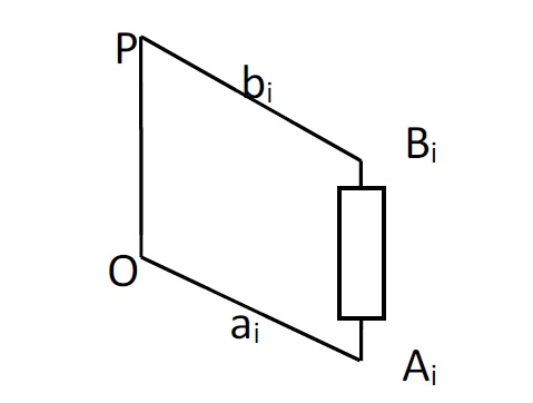
Li: The length of the passive segment for i=1,2,3 (Figure 3).
Figure 3: Represents the link between the “i” segment and the plat-form.
By developing the equation (15), we will have the following relationship:
Où:
To simplify the form of expression, we define:
Note: For our manipulator e5=e4, e7=e8
The lengths of the expandable segments can be expressed as follows:
Equations (18) accurately represent the inverse geometric model of our constrained robot. Therefore, given the geometric dimensions of the parallel robot, we can determine the lengths of the active segments that are needed to move the mobile platform to the point of the working area located at the coordinates (Px, Py, Pz).
Expressions (18) allow us to implement the robot command based on the inverse geometric model. We pose: qi=q2,
Workspace
The workspace of parallel robots is limited by three types of constraints:
- - The length of the active segments.
- - Mechanical stresses on passive joints.
- - Segment interference.
The general principle of calculating the workspace for a constant-orientation manipulator is to assume that the constraints on a chain i make it possible to define the volume Vi that can be reached by the point Bi, the point of attachment of the chain to the plateform. When the point Bi describes this volume, the point P describes an identical volume Vip obtained in translation Vi by the vector BiP which is constant since the orientation is constant [11-14]. This volume is the volume of work allowed for the point P with respect to the constraints on the “i” segment. The workspace is the one where the constraints on the whole segment are verified, it is thus obtained by the intersection ViP. For simplicity, we calculate the intersections of each of the Vip with the cutting plane and we proceed to the intersection of the resulting elements [6].
Equations (19) are rewritten in the following form:
Each of the expressions (20) represents a sphere in the space (x,y,z) of radius qi; the center of the mobile platform is at the intersection of the three spheres.
The cylinders have a minimum length qimin and a maximum length qimax, so the workspace is the set of intersections of the three annular zones delimited by the boundaries of the spheres of rays qimin and qimax.
The first equation delimits an annular zone whose boundary is a central sphere and radius q1 max and the inner border a sphere of the same center and radius q1 min.
The second equation is a center sphere , it delimits an annular zone whose outer radius boundary q2 max and the inner boundary a sphere of the same center and radius q2 max.
Similarly, if we consider the third equation, we see that it delimits an annular zone whose outer boundary is a central sphere. q3 max and radius q3 max , and the inner boundary, a sphere of the same center and radius q3 max .
Reconfiguration
A geometrical reconfiguration of the Constraint parallel robot reconfigurable to 3d.d.l is executed from the inverse geometric model, adjusting simultaneously and symmetrically the lengths of the three kinematic chains.
It is important to mention that each reconfiguration is achieved by changing only the length of the respective link, while maintaining the remaining lengths fixed [15-18].
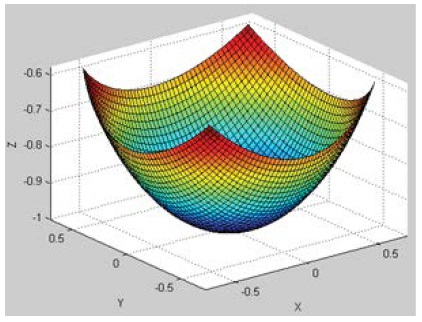
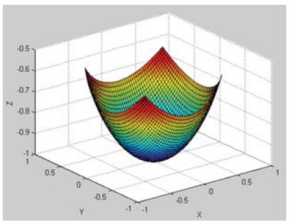
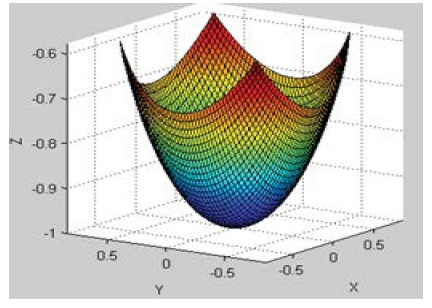
Figures 4-6 show the resulting variations in the working area for variations of the radius of the platform R, corresponding to the values: 50, 250 and 350 mm.
Figure 4: Working area corresponding to R = 50 mm.
Figure 5: orking area corresponding to R = 250 mm.
Figure 6: Working area corresponding to R = 350 mm.
It can be said that the maximum working area is obtained when R=50 mm.
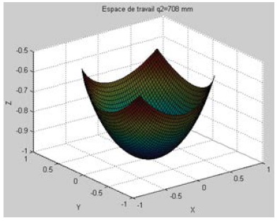
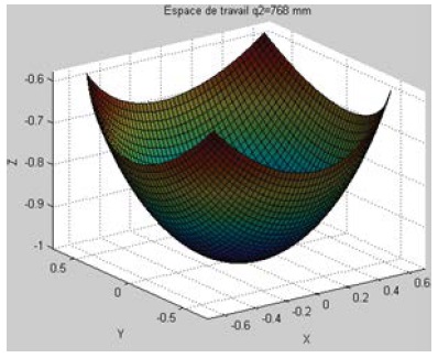
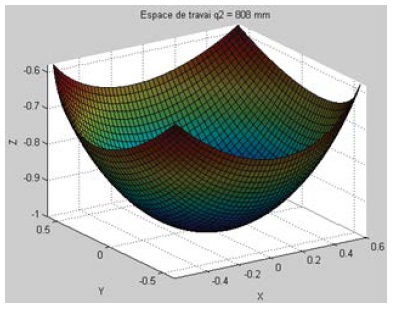
For the reconfiguration of the parameter q2 (or parallelogram) from equations (19), a change of the working space is obtained when the length of the link varies from 648 to 825, as can be seen, by increasing the value of q2, the workspace increases by about the same proportion (Figure 7-9).
Figure 7: Workspace corresponding to the reconfiguration of q2 = 708 mm.
Figure 8: Workspace corresponding to the reconfiguration of q2 = 768 mm.
Figure 9: Workspace corresponding to the reconfiguration of q2 = 808 mm.
Although there is an increase in both the workspace and the maximum range along the X, Y, and Z axes.
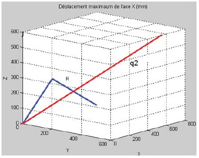
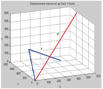
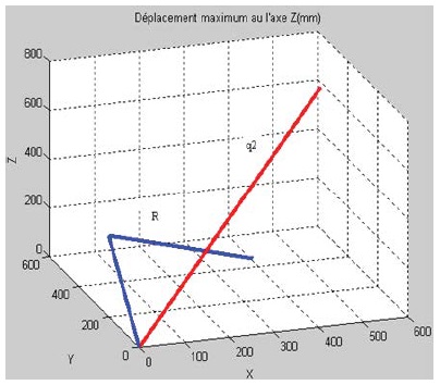
From equation (19), which express the articular variables as a function of the position parameters of the platform. The maximum displacement along the axis (X, Y, Z) is determined.
The design of a reconfiguration mechanism that dynamically modifies the q2 parameter by means of a single actuator seems rather difficult or almost impossible. On the other hand, reconfiguring the R parameter causes a significant change in the shape and volume of the workspace (Figure 10-12).
Figure 10: Maximum displacement of the X axis (mm).
Figure 11: Maximum displacements of the Y axis (mm).
Figure 12: Maximum displacement on the Z axis (mm).
Mechanism of reconfiguration
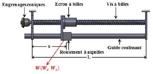
Our reconfiguration mechanism consists mainly of a ball screw, rotated through a bevel gear pair and guided in translation by a sliding guide on a needle bearing (Figure 13).
Figure 13: Mechanism of reconfiguration.
Conclusion
The work presented in this article was devoted to the inverse geometrical modeling of a reconfigurable constrained parallel robot with 3 ddl and to the study of reconfigurations as well as the variations of the working area. To accomplish this task, we considered the reconfigurable parallel robot constrained to 3d.d.l as a closed-loop structure. We chose to model it in a different way by studying more closely the structural characteristics of this robot. This study allowed us to describe it in a systematic way, and to establish geometric relations between the two elements that make up the parallel structure: the platform and the segments (the active segments and the passive segment).
However, we quickly calculated the reconfiguration of the robot. To accomplish this task, we considered symmetry of all kinematic chains, which allowed us to use a single actuator.
Renaud P, Vivas A (2006) Kinematic and dynamic identification of parallel mechanisms. J Control Engg Practice 14: 1099-1109. [ Ref ]
Voigt HM, Santibanez-Koref I, Born J (1992) Hierarchically structured distributed genetic algorithm. Elsevier Science Publishers pp: 145-154. [ Ref ]
de Lamotte F (2006) Proposition d’une approche haute niveau pour la conception, l’analyse et l’implantation des systèmes reconfigurables, Thèse présentée à l’Université de Bretagne pp. 19-56. [ Ref ]
Selvakumar AA, Kumar MA (2014) Experimental investigation on position analysis of 3 – DOF parallel manipulators. Science Direct 97: 1126-1134. [ Ref ]
Maya M, Castillo E, Lomelí A (2012) Workspace and Payload-Capacity of a New Reconfigurable Delta Parallel Robot. International J Advanced Robotic Systems. [ Ref ]
Yangt G, Ming Chenj I, Lim WK, Yeo SH (1999) Design and kinematic analysis of modular reconfigurable parallel robots. Intemational Conference on Robotics & Automation, Detroit, Michigao. [ Ref ]
Cherfia A, Zaatri A, Giordano M (2006) Kinematics analysis of a parallel robot with 3 DOF and 4 segments in pure translation. MEJ 31: 102-110. [ Ref ]
Borojéni D (2006) Modélisation cinématique et dynamique des systèmes Poly-Articulés à chaines ouvertes ou fermées. cas des robots parallèles, thèse présentée à l’Université Paris pp : 31-34. [ Ref ]
Cherfia A, Zaatri A, Giordano M (2007) Kinematics analysis of a parallel robot with a passive segment. Ingeniare Rev Chil Ing 15: 141-148. [ Ref ]
Ibrahimi O (2006) Contribution à la modélisation dynamique des robots parallèles et des robots hybrides. Thèse présentée à l’Université de Nantes pp: 28-64 [ Ref ]
Scheitzer M, Puig-verges N (2018) La robotique dévloppmentale et l’intelegence artifielle conduiront elles à l’émengence de nouvelles valeurs pour l’homme 3: 291-295. [ Ref ]
Thompson D, Mundy J (1987) Modèle tridimensiel corrrespondant à partir d’un point de vue non contraint. Robotique et Automatisation Procédure Confférence Internationnel de 4: 208-220. [ Ref ]
Wissama K (1999) Modélisation, identification et commande des robots, 2éme édition revue et augmentée pp : 201-215.1999. [ Ref ]
Joshi SA and Tsai LW (2003) The kinematics of a class of 3 DOF, 4-legged parallel manipulators. J Mechanical Design 125: 52-60. [ Ref ]
Takamori T and Tsuchiya K (1993) Parallel manipulators: state of the art and perspective. Robotics Mechatronics and Manufacturing Systems, Elsevier. [ Ref ]
Merlet JP (1999) Determination of 6D workspaces of Gough-type parallel manipulator and comparison between different geometries. Int J Robotics Res 18: 902-916. [ Ref ]
Merlet JP (2004) Guaranteed in-the-workspace improved trajectory/ suface/volume verification for parallel robots. Int Conf on Robotics and Automation, New Orleans, USA. [ Ref ]
Pavicic M, Merlet JP, Megill ND (2004) Exhaustive enumeration of Kochen-Specker vector systems. Technical Report-5388, INRIA pp: 39. [ Ref ]
