Journal Name: International Journal of Nano Research
Article Type: Research
Received date: 14 January, 2019
Accepted date: 21 January, 2019
Published date: 28 January, 2019
Citation: Ching-Wei C, Chia-Ray C. (2018) Comprehensive Design and Analysis of a RC-Cassegrain Telescope for Micro-Satellite Mission. Int J Nano Rech Vol: 2, Issu: 1 (01-05).
Copyright: © 2018 Ching-Wei C. This is an open-access article distributed under the terms of the Creative Commons Attribution License, which permits unrestricted use, distribution, and reproduction in any medium, provided the original author and source are credited.
Abstract
Optical design of a reflecting telescope for use in a Micro-Satellite mission is reported in this study. A Ritchey-Chretien (RC) Cassegrain telescope for earth observation techniques is adopted in this design. The primary and secondary mirror are circular clear apertures with 380 mm and 140 mm in diameter. The effective focal length is 2525 mm operated at 561 km altitude. Two commercial 25k CMOS image sensors with pixel size of 4.5 μm are applied, which capture a corresponding 5 km + 5 km swath area. The ground resolution is moderate to be 1 m and 2 m for PAN and MS applications. The MTF is expected to be about 0.3 at camera Nyquist frequency at 111 lp/mm. The tolerance analysis is performed for further understanding on fabrication and assembly errors. The defocus and LOS equations are also evaluated in this study. These analytical results are the important reference in Micro-Satellite mission for self-reliant space technology development in Taiwan.
Keywords
Ritchey-Chretien (RC) Cassegrain telescope; Optical design; Tolerance analysis; Space optics.
Introduction
Taiwan’s government encourages National Space Organization (NSPO) to actively promote local space industry in the upcoming 10 years space program, so NSPO try a promising approach for the new remote sensing satellite program. NSPO executes a Micro-satellites program which promote the cooperation with domestic academia and industry to develop the space components, subsystems, system, and forming space industry in Taiwan. Most of the satellite key components will be designed and made in Taiwan. Flight and technology demonstration of self-reliant key components, satellite system, and mission concept in 2022 is important. That will be the first space program in Taiwan aiming to the promotion of space industry locally. If everything goes well, upcoming five Micro-satellites will be developed and launched for science missons from 2023-2027. The fully deployment of six satellites can provide good earth observation services for the users in Taiwan and other countries.
This paper describes the design and comprehensive analysis of a Ritchey-Chretien (RC) Cassegrain telescope for earth’s observation with Micro-satellites mission. Section 3 describes the basic requirement for the Micro-satellites optical system. Section 4 reports the optical design, optical performance calculations and tolerance analysis. Section 5 concludes this paper.
Basic Requirements for the Microsat Telescope Optical design concept
The main purpose of this telescope optical system is a fine ground sampling distance resolution image of earth’s surface with the Microsatellites application. The primary purpose of the optical module is to record wide and broadband images of a scene around the satellite. For the reason of easy fabrication and advantages of alignment and compactness, the RC Cassegrain type (catadioptric type), which is a combination of refraction and reflection using lens and curved mirrors, is primary consideration. The telescope characteristics are determined by the ground resolution goal, the image sensor hypothesis and the image requirements. Table 1 shows the optical design specifications of the telescope. The orbit altitude is 561 km, focal length is 2525 mm, which corresponds to PAN GSD 1 m due to the sensor pixel size 4.5 μm. Therefore, the angular resolution is 1.78 microrad. The clear aperture of primary and secondary mirrors is 380 mm and 140 mm. The ground resolving distance in this design is approaching diffraction limit. The field of view (FOV) is ±1° in this optical system. We set the focal image plane area to be about 88 mm in diameter, which could accommodate two sets of the image sensor active areas. As a result, the swath could be enlarged as 5 km + 5 km for better earth observing capability.
Table 1: Design specifications of the telescope.
| Parameters | Specifications |
|---|---|
| Orbit altitude | 561 km |
| Swath | 5+5 km |
| GSD | 1m @ PAN & 2m @ MS 1m @ PAN & 2m @ MS (binning mode) |
| M1 clear aperture | 380 nm |
| M2clear aperture | 140 nm |
| Sensor pixel size | 4.5 µm (binning capability) |
| Focal length | 2525 mm |
| FOV | ±1° |
| Telescope type | RC Cassegrain (catadioptric) |
Image sensor
The main goal of this remote sensing system is to obtain high quality image of earth’s surface with the low cost COTS device in Micro-satellite platform. Our observation target is the day time earth surface, which is bright enough to allow collection of images with CMOS image sensors in the designed telescope. For our optical design, we choose the CMOS image sensor NOIP1SN025KA produced by ON Semiconductor [1]. The pixel size is 4.5 μm × 4.5 μm and the pixel array is 5120 × 5120. This sensor allows pixel binning capability and image output on random programmable region of interest. Table 2 gives a description of the CMOS image sensor specifications used in our design.
Table 2: Imaging sensor specifications.
| Items | Specifications |
|---|---|
| Active array size | 5120 × 5120 |
| Pixel sixe | 4.5µm × 4.5µm |
| Temperature range | ˗40°C~85°C |
| Image area | 23mm × 23mm |
| Analog to Digital Converter (ADC) | 10 bit |
| Capability | Random Programmable Region of Interest (ROI) |
Optical Design and Analysis
Telescope design
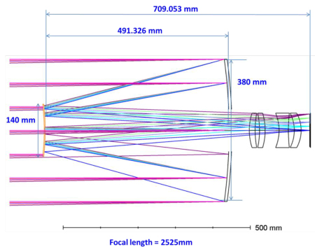
Optical design or lens design is the process used to find the best set of lens construction parameters (eg., radii of curvature, thicknesses, airspaces, and materials) that optimizes the overall performance and manufacturability of an optical system [2]. The telescope is designed as catadioptric telescope, which means the use of lenses and mirrors. The system consists of a parabolic primary mirror, a second mirror hyperboloid and corrector lenses which used as eliminating aberration. One of the advantages of using a RC Cassegrain system is it can decrease aberrations of lens. We used a round shape 380 mm and 140 mm clear aperture in diameter mirrors as the telescope’s primary (M1) and secondary (M2) mirrors. The distance between M1 and M2 is 491 mm. Moreover, four corrector lenses are used to compensate the aberration and improve the image quality at off-axis large field angle. The total length in the optical design is 709 mm. This design is quite compact. The axial dimension is close to four times smaller than the focal length. Figure 1 shows the design layout of the Micro-satellite telescope.
Figure 1: Optical design layout of the Micro-satellite telescope.
Optical performance analysis
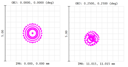
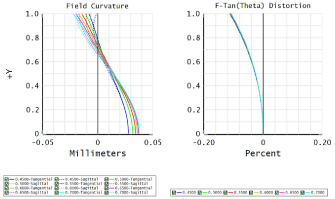
The analysis was carried out with the Zemax optical design program. Figure 2 depicts a spot diagram that includes the size and shape of the spot for 0.65 μm wavelength. The RMS radius of the central (0°, 0°) and the outer fields (0.25°, 0.25°) are 0.554 μm and 0.703 μm, respectively. The field curvature and F-Tan (Theta) distortion are also presented in Figure 3. The maximum distortion is lower than 0.12% around the full field.
Figure 2: Spot diagram at different fields. Square box is 5μm × 5μm.
Figure 3: Field curvature and F-Tan (Theta) distortion. Solid-line and dashline are for tangential and sagittal for all wavelengths, respectively.
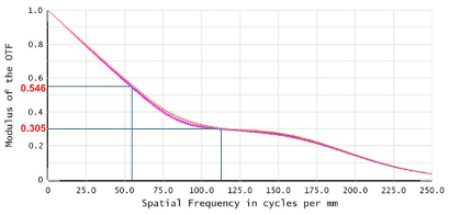
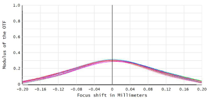
The MTF diagram is shown in Figure 4, where the solid line is the MTF value of the tangential component of the curve, and the dashed line is the sagittal component of the curve. The optical design is almost close to diffraction limit. The MTF value appears about 0.305 at the sensor Nyquist frequency 111 lp/mm. In this case, the tangential and sagittal MTF are a little bit different, which is due to the different length in x and y direction of baffle obscuation. Figure 5 presents the through focus MTF of this optical system at spatial frequency 111 lp/mm. There is only less than 20% degradation of MTF value when the focus plane has ±60 μm displacement. In fact, the thermal refocusing mechanism is applied to secondary mirror to achieve the position adjustment of focal plane to maintain the good MTF and optical performance in Micro-satellite.
Figure 4: Diffraction MTF.
Figure 5: MTF through focus at frequency 111 lp/mm.
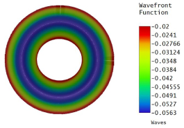
The interferometric pattern of optical path difference (OPD) is also evaluated in the optical analysis. Figure 6 shows the on-axis (0°, 0°) wavefront error, and Zernike polynomials fitting coefficients are also represented in Table 3. From the fitting analysis, the peak to valley wavefront error is 0.0351 λ and root-mean-square wavefront error is 0.0097 λ, where the λ is 0.65 μm. This optical design shows a little bit spherical aberration, the other high order aberration such as coma, astigmatism is quite small.
Table 3: Zernike fringe polynomials fitting.
| Surface | Image | |
|---|---|---|
| Field | (0, 0) degree | |
| Wavelength | 0.65 µm | |
| Peak to valley | 0.0351 waves | |
| RMS | 0.0097 waves | |
| Z1 | ˗0.04226 | 1 |
| Z2 | 0 | (ρ) * COS (A) |
| Z3 | 0 | (ρ) * SIN (A) |
| Z4 | ˗0.02515 | (2ρ2˗1) |
| Z5 | 0 | (ρ2) * COS (2A) |
| Z6 | 0 | (ρ2) * SIN (2A) |
| Z7 | 0 | (3ρ2˗2) ρ * COS (A) |
| Z8 | 0 | (3ρ2˗2) ρ * SIN (A) |
| Z9 | 0.01578 | (6ρ4˗6ρ2+1) |
| Z10 | 0 | (ρ3) * COS (3A) |
| Z11 | 0 | (ρ3) * SIN (3A) |
| Z12 | 0 | (4ρ2˗3) ρ2 * COS (2A) |
| Z13 | 0 | (4ρ2˗3) ρ2 * SIN (2A) |
| Z14 | 0 | (10ρ4˗12ρ2+3) ρ * COS (A) |
| Z15 | 0 | (10ρ4˗12ρ2+3) ρ * SIN (A) |
| Z16 | ˗0.00134 | (20ρ6˗30ρ4+12 ρ2˗1) |
Figure 6: Optical path difference (OPD).
Tolerance analysis
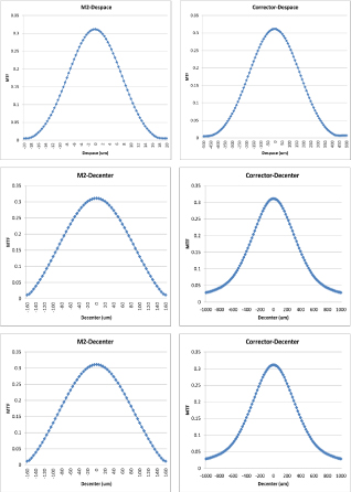
The importance of tolerance analysis is to improve the practicality and reliability of optical design [2]. Tolerance analysis not only avoids the existence of sensitive elements in the system but also predicts the performance under fabrication and assembly precision limitations. Compared to non-symmetrical design, the symmetrical design helps to loosen the production and assembly tolerance. In this paper, the tolerance analysis, which indicated the predicted optical performance, is performed on manufacturing and alignment errors of the RC Cassegrain telescope. Secondary mirror (M2) and corrector lens are separately analyzed the MTF degradation by despacing along z-axis, decentering along x-axis and tilting along y-axis, respectively. The 20% degradation of MTF value for secondary mirror is ±5 μm for despace, ±50 μm for decenter and ±300 μrad for tilt. Corrector lenses show the less sensitive for the same tolerance analysis. It is ±115 μm for despace, ±210 μm for decenter and ±1400 μrad for tilt, respectively. (Figure 7)
Figure 7: Despace, decenter and tilt tolerance analysis for secondary mirror and corrector lenses.
Combined the sensitivity analysis and Monte Carlo calculations, the degradation of MTF and wavefront errors could be investigated under the allocation of system tolerances. The tolerances allocation in Table 4 meets the fabrication facility precision limitations and practical assembly experiences [3]. In practical, the fabrication accuracy of the radius of mirrors could be controled within 0.1%. The analysis results indicate that the most sensitive is the deviation of mirror radius. The other factors, such as deviation of corrector suface radius, thickness, irregularity and alignment errors, do not degrade the optical performance much. In fact, the deviation of radius of primary and secondary mirror will result in the defocus of image plane. The defocus effect could be eliminated in focal plan assembly (FPA) alignment and intergraion stage of the satellite. Therefore, this design of RC Cassegrain telescope system after the practical fabrication and assembly process could still meet the specification. The tolerance analysis is a valuable reference for the future fabrication and assembly.
Table 4: The tolerances allocation on manufacturing and alignment.
| Tolerance term | Sub Tolerance term | Objects | Tolerances |
|---|---|---|---|
| Manufacture | Radius (mm) | M1 | 1.4 |
| M2 | 0.59 | ||
| Corrector #1 | S1: 0.15 S2: 0.26 |
||
| Corrector #2 | S1: 0.21 S2: 0.16 |
||
| Corrector #3 | S1: 0.12 S2: 0.42 |
||
| Corrector #4 | S1: 0.10 S2: 0.094 |
||
| Thickness (mm) | Corrector #1 ~ #4 | 0.025 | |
| Irregularity (fringe) | M1 & M2 | 0.11 | |
| Alignment | Decenter X and Y (mm) | M2 | 0.015 |
| Tilt X and Y (degree) | M2 | 0.004 | |
| Decenter X and Y (mm) | Corrector #1 ~ #4 | 0.05 | |
| Tilt X and Y (degree) | Corrector #1 ~ #4 | 0.016 |
Line-of-sight (LOS) jitter is the time-varying motion of the image on the sensor plane [4], which may be caused by internal or external dynamic loads acting on an optical system. Image jitter degrades optical performance by increasing the blur diameter of the point spread function (PSF). This results in blurring of the object and loss in resolution. As a result, the MTF curve will degrade. In this study, we are considering transverse image motion or motion in the plane of the sensor. However, vibratory loads may also induce longitudinal image motion or defocus that displaces the image along the optical axis. Therefore, the formula of transverse and longitudianl image motion, such as LOS and defocus, on optical system performance is depicted in the followings.
The LOS in x- and y-directions are described as follows:
θyLOS(μrads) = -0.396*δxFPA+1.397*δxM1-0.969* δxM2- 0.032 δxL+1.979*θyM1-0.591θyM2+0.001*θyL
θxLOS(μrads) = -0.396*δxFPA+1.397*δxM1-0.969* δxM2- 0.032 δxL-1.979*θyM1+0.591θyM2-0.001*θyL
The parameters are list in Table 5.
Table 5: Sensitivity matrix for LOS formula.
| Symbol | Unit | Definition |
|---|---|---|
| δxFPA | µm | The displacement of FPA along x-axis |
| δx M1 | The displacement of primary mirror along x-axis. | |
| δxM2 | The displacement of secondary mirror along x-axis. | |
| δxL | The displacement of corrector lens module along x-axis. | |
| θyM1 | µrads | Tilt angle of the primary mirror (M1). The axis of rotation is y-axis. |
| θyM2 | Tilt angle of the secondary mirror (M2). The axis of rotation is y-axis. | |
| θyL | Tilt angle of the corrector lens module. The axis of rotation is y-axis. | |
| θyLOS | Jitter in object space. The axis of rotation is y-axis. |
The defoucs in z-direction (on-axis) is also given as follows:
Defocus(μm) = 13.765*δZM2-12.605*δZM1-0.160*δzL-1.000*δzFPA-6.308*δzM1+3.067*δzM2
The parameters are list in Table 6.
Table 6: Sensitivity matrix for defocus formula.
| Symbol | Unit | Definition |
|---|---|---|
| δZM1 | µm | The displacement of primary mirror along z-axis. |
| δZM2 | The displacement of secondary mirror along z-axis. | |
| δZL | The displacement of corrector lens module mirror along z-axis. | |
| δZFPA | The displacement of FPA along z-axis. | |
| δRM1 | The change in radius of primary mirror. | |
| δRM1 | The change in radius of secondary mirror. |
According to LOS and defocus formula described above, it could be conveniently and accurately to estimate the overall jitter effect on optical components in telescope due to the possible thermal and vibrational effects. By use of these formula, we can deduce the optical performance degradation under thermal distortion to simulate the practical Microsatellite behaviors on the orbit.
Conclusion
We present the optical design of a RC Cassegrain telescope for Micro-Sattelites application in this study. The commercial COTS image sensors used in this design are for the reason of low cost requirement. It uses a symmetrical RC Cassegrain type optical telescope, and its MTF is expected to be about 0.305 at sensor Nyquist frequency. The results represent the good optical performance such as small field curvature, distortion and high-order aberrations. This telescope shows a reasonable design to obtain a more detailed image with a Micro-Sattelite. The tolerance analysis indicates that the designed telescope system after the practical fabrication and assembly degradation process still meets the specification. LOS and defocus formula is helpful for future study of thermal distortion analysis on this project. These results will be used in space exploration with Micro-satellites mission.
There are no references
