Journal Name: Journal of Multidisciplinary Research and Reviews
Article Type: Research
Received date: 28 October, 2019
Accepted date: 11 November, 2019
Published date: 18 November, 2019
Citation: Micus S, Pachl H, Haupt M, Gresser GT (2019) Locally LSR Over-Molding of Textile Integrated Actors and Sensors. J Multidis Res Rev Vol: 1, Issu: 2 (106-112).
Copyright: © 2019 Micus S. This is an open-access article distributed under the terms of the Creative Commons Attribution License, which permits unrestricted use, distribution, and reproduction in any medium, provided the original author and source are credited.
Abstract
The protection of electronics against environmental influences and mechanical loads is important for integration of conventional electronics in textile conductive tapes. For this purpose, the sensors on the tapes are molded with plastic locally. This process step is recognized in the injection molding process. The molding compound is then later selected depending on: The field of application, the parameters of the manufacturing process and the textile tape properties. We have designed a mould for liquid silicone (LSR) as well as for the textile and electronic insertions. The cavities are sealed by a local compression of the textile and the two inserts are positioned with position pins representing the main aspect of the mould design. The sampling tool and the process parameter optimization are mainly based on the material properties of the silicone and the mechanical sensitivity of the inserts. To reduce the deformation of the circuit boards by the melt front and ensuring the functionality of the electronics a low-pressure process is used.
Keywords
Injection molding; Smart textiles; e-textiles; Integration of electronics in textiles.
Introduction
A current trend in product development is the integration of different functionalities in one system [1]. A popular example is the combination of telephones and photography in smartphones. For textiles, is the integration of intelligent functions like sensors or lighting. These Smart Textiles are applied in many new fields, for example in sectors like medicine, automobiles, sportswear, protective clothing and fashion. The challenge is to obtain the usual properties of the textile such as haptic, wash ability [2], wearing comfort and drape ability. At the same time, the textile must be able to endure changing environmental influences. We have recognized that by contacting printed circuit boards (PCB) with conductive structures in a textile tape. These boards are equipped with a variety of sensors or LEDs. We have locally over-moulded the tapes with polymer to protect the circuit boards and the sensitive contact areas. Previously, this process was carried out manually. The injection molding process is automated, enabling shorter cycle times and reproducible quality. Care must be taken that neither the electronic components nor the electrically conductive textile are damaged during the process by effective pressures and temperatures.
Relevant environmental influences experienced by textiles and integrated electronics including the effects of liquids such as water, chemicals or gases. For this reason, it is important to ensure that the mould is impermeable and that the polymers have a corresponding barrier effect (diffusion barrier). Furthermore, sensitive electronic components must be protected from mechanical influences such as vibration or foreign objects. Extreme temperatures can also be harmful for the electronics. High-temperature plastics can serve as protection because they have a high thermal resistance.
State of the Art
Over-molding of electronics
Electronic components are often moulded with plastic to protect them from environmental influences. In many fields of application, the components must be sealed against fluids to ensure their functionality. This is achieved in the injection molding process with a compatible polymer. The ability to automate the process is advantageous. This makes it possible to produce large series and guarantee reproducible quality. The fixation of the inserts in the mould is technically a complex procedure. This can be achieved by placing the insert in bores or on pins and bars. Alternatively, Snap-on devices, magnets or the application of vacuum are used [3]. Difficulties arise when setting up the process. High temperatures cause the soldered joints to melt and high injection pressures cause impermissibly high mechanical stress on the components [4]. It is therefore recommended to carry out preliminary tests with the inserts in order to determine their maximum temperatures [5-8]. The mechanical stress caused by the injection and packing pressure can also damage the electronics, so the pressure is kept low [8].
To avoid these problems, a suitable material is required. One of the materials used is duroplastics, which can be processed at low temperatures [8]. Duroplasts is dimensionally stable over a wide temperature range, absorb almost no water, function as an electrical insulator and have good media resistance. Sensors which are used in the automotive industry are protected like this [9]. Other materials used for over-molding electronics are thermoplastic elastomers [10].
Over-molding of textiles
Polymer is used in injection molding of textile inserts with electrical conductive structures. For example, a plastic USB connector is already being produced on a textile tape in a two-stage injection molding process. For this purpose, the textile is covered with the compound. In the first process step, the contact points between the conductive textile and the connector pins are injected with a conductive polymer. In the subsequent second injection molding process, a mechanical connection and at the same time the insulation of the connector pins against each other with a different material is achieved. The aim is to protect the plug connection and to miniaturize the connection in order to achieve only minimal local stiffness of the textile by the plastic. In mould construction, it must be ensured that the transition from the injection moulded part to the textile is smooth. This is the only way to reduce stress peaks and buckling forces. A flexible plastic should be selected for the same reason. In order to prevent high loads in the textile, there must only be a small difference in strength between the two components. Another aspect is the stress on the textile caused by high temperatures and pressures during the filling process.
A difficulty occurring in mould construction is sealing the cavity, as the tape protrudes over it. The melt should be prevented from flowing further into the textile than intended by the mould. For the textile tape, a gap is made in the mould. This gap is thinner than the thickness of the textile, as the textile is compressed with a correspondingly high closing force. Textiles are compressible and therefore seal with a correspondingly high press force. Furthermore, the textile can be moved by the melt during the filling process, causing it to require fixation. This can be achieved, for example, with needles in the mould on which the tape is placed. In summary, many problems exist when encapsulating textile-integrated electronics. These include low dimensional accuracy, rough tolerances, different insert thicknesses, sealing the cavity and fixing the tape. All these aspects result from the advantages of textiles. These include the flexibility, drapability and haptic of the textile, so that special handling is necessary[5-7].
Methods and Materials
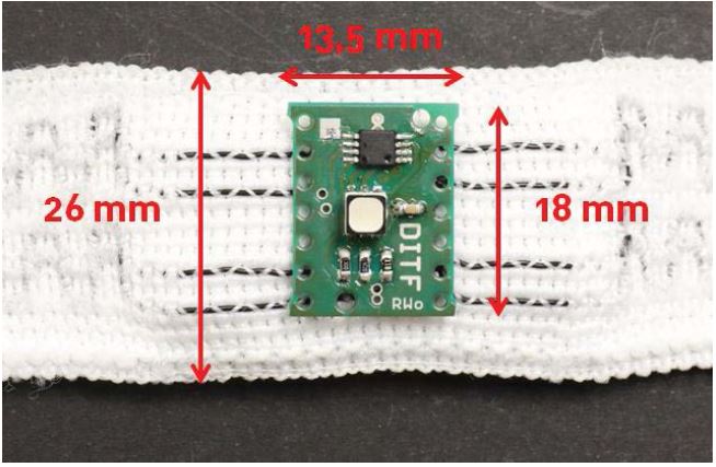
We manufacture textile tapes equipped with non-textile sensors. It is a flexible textile tape with conductive structures in it. A CO2 laser strips these tapes at specific points and removes the surrounding textile. Sensors are soldered to these points, creating a mechanical and electrical connection. This contact is mechanically sensitive. The plastic coating is to protect these contact points from mechanical stress. In addition, we have to protect the integrated sensors from environmental influences. For this purpose, we construct an injection mould which is compatible with the inserts (textile tape and circuit board) and the molding compound (liquid silicone rubber). The integrated circuit boards are equipped in several ways. We use RGB LEDs, acceleration or temperature sensors, etc... A bus system controls the sensors and actuators so that communication between the LEDs and the sensors is possible. A plug is also attached to the end of each band. This allows the tape to connect to a data acquisition and data processing system Figure 1.
Molding compound
We select the molding compound according to various criteria. On one hand, the material should have certain elasticity. This ensures that the textile is subjected to less stress during bending. The difference in strength between the connected components is therefore kept to a minimum. For this reason, we choose a material from the group of elastomers. On the other hand, the material should also be biocompatible because the tapes are worn on the body.
In order to prevent a short circuit, a material with insulating properties is selected. Furthermore, the material should be injection molding process friendly. Other requirements are from the respective field of application in which the textile is used. These include properties such as media resistance and tightness, as well as a good heat resistance. On the basis of these aspects we have chosen Silicone.
We use a LSR Silicone: Elastosil LR 3003/80 from Wacker Chemie AG. It has a shore hardness of 80 and a usage temperature range of -55°C to 210°C. It is also suitable for injection molding due to its short vulcanization time and is biocompatible.
Figure 1:Picture of the inserts (textile tape and circuit board) and dimensional data.
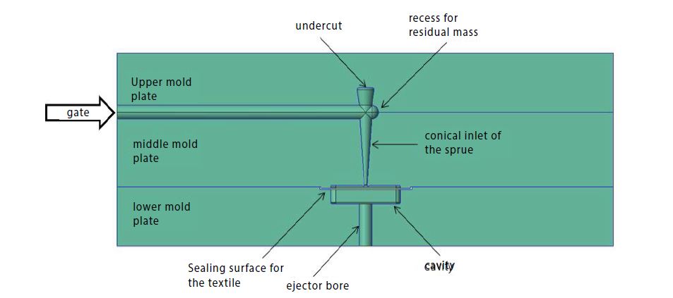
Figure 2:The feed system.
Mould construction
We construct a three platen mould with two horizontal parting lines because we use the Babyplast vertical machine. One parting line is used to demould the feed system. The cavity is located in the second parting line Figure 2.
The cavity surrounds the circuit board. We selected the dimensions so that the moulded part protrudes 2 mm beyond the circuit board. In order to take the rheological properties of the polymer melt into consideration, the cavity is rounded. The textile tape is placed in the cavity so that the melt flows vertically onto the textile and the textile is therefore on the sprue side. This makes it easier to position the circuit board. It is placed directly on the positioning pins. The melt flows through the textile, around and under the circuit board. A self-releasing point gate is installed in the mould. It is an undercut in the upper mould plate and a latch locking unit enables the moulded parts and the feed system to be demoulded after each shot. As an insertion aid, there is a bearing surface for the textile band in the lower mould plate and four needles at the outer ends on which the textile band can be placed. This fixes the textile band in the mould.
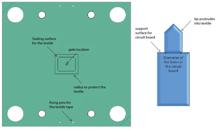
The greatest challenges are sealing the cavity and positioning the circuit board in the mould during the process. When processing with silicone, gap widths of less than 0.01 mm are normally required, which are not possible here because of the textile insert. Even the application of vacuum to the cavity is not possible. Alternatively, venting occurs via the ejector bore. The low viscosity of the material tends to form burrs in the parting lines. This should be avoided with a suitable clamp force on the tape. The tape is located in a gap between the lower and middle forming plates, which is thinner than the tape thickness. In addition, we designed a sealing surface around the cavity Figure 3.
This additionally compresses the tape, by reducing the sealing surface around the circuit board. The same force acts on a smaller surface. This therefore increases the surface pressure. Care must be taken that the clamping force does not damage the conductive structures in the tape and loose connections due to a cable breaking. In addition, a radiprovided at the edges of the sealing surface to protect the textile. To position the circuit board during the process, we construct three pins into the cavity. Bevor every injection we plug the pins into the bores in the circuit board. This raises the circuit board to the appropriate height. With the appropriate software, these pins can be pulled by using a core pull after the injection phase; the gaps are filled by using the packing pressure.
Figure 3:The sealing surface in the lower mould plate and the positioning pins.
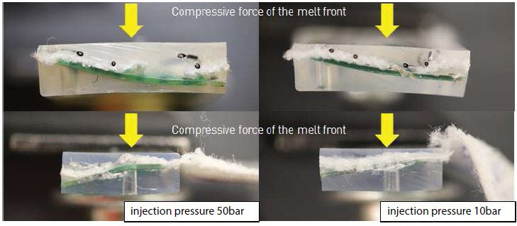
Figure 4:Deformation of the circuit board caused by variation of the injection pressur
Process analysis
In terms of process parameters, the injection molding process with liquid silicone rubber is essentially different from processing with thermoplastics. Due to the low viscosity of silicone, lower injection pressures are required than in the processing with thermoplastics. The mould temperature is between 160°C and 220°C to start the vulcanization reaction. Liquid silicone rubber has negligibly low reaction shrinkage, while the usual packing pressure for mould filling is almost dispensed. Instead, thermal dilatation occurs, which causes the material to expand. The packing pressure is therefore only used to prevent the melt from flowing back into the screw vestibule. The volume expansion of the material can result burr formation, so that the cavity has to be filled under volumetrically. The melt cushion is set to zero so that the packing pressure does not press any material into the cavity and the mould is overfilled [11,12].
The process is designed with regard to the functionality of the inserts, because they are thermally and mechanically sensitive. The vertical flow front deforms the circuit board and the textile. The solder joints can also be damaged. We create a low-pressure injection molding process to minimize the mechanical stress on the inserts. The basic settings of the process parameters are largely determined empirically. The shot volume is taken from the CAD geometry and set slightly lower for the first shots. Subsequently, the metering path is increased until burr formation occurs. Due to the deflection of the circuit board, we gradually reduce the pressure. Finally, the lowest possible injection pressure of 10 bars is used. The packing pressure is also set to 10 bars Figure 4.
Just like the injection pressure, the injection speed also equals the lowest machine setting parameter. Higher injection speeds produce air traps below the circuit board Table 1.
Table 1:Default settings of the injection molding process.
| Process parameter | Unit | Value |
|---|---|---|
| injection pressure | bar | 10 |
| packing pressure | bar | 10 |
| melt cushion | mm | 0 |
| mould temperature | ºC | 190 |
| vulcanization time | s | 30 |
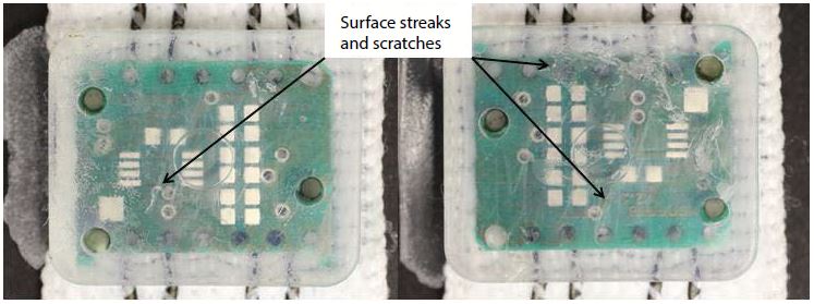
Figure 5:Surfaces of test series 1 (left) and test series 2 (right) of the full factorial test plan.
Table 2:Full factorial test design with variation of packing pressure and mould temperature.
| Injection test | Packing pressure | Mould temperature | |||
|---|---|---|---|---|---|
| Experimental procedure | 1 | (-) | 10 | (-) | 190 |
| 2 | (+) | 20 | (-) | 190 | |
| 3 | (-) | 10 | (+) | 200 | |
| 4 | (+) | 20 | (+) | 200 | |
The default settings are used to produce products that have a sink mark and poor surface quality. On the sprue side, the surface curves inwards. The surface is characterized by striations and a milky colour. In some cases, surface damage can also be caused by unevenness in the mould cavity. A full factorial test plan (Design of Experiments) is intended to avoid the sink marks on the moulded part and to improve the surface quality. The packing pressure is varied by setting a small melt cushion of 0.5 mm. This packing pressure should push out the sink mark. In addition, an increased tool temperature is tested to improve the surface quality Table 2.
Results and Discussion
With statistical Design experiments, optimized settings are tested in order to systematically eliminate these quality deficiencies. The sink mark cannot be avoided by increasing the injection pressure or the injection speed, otherwise new error patterns will occur.
If the injection pressure is too high, the circuit board is bent excessively, therefore this parameter is no longer adjusted. If the injection speed is set too fast, air traps accumulate under the circuit board because the air has no time to vent through the holes for the ejector pin and the positioning pins. Instead, the packing pressure is increased to push out the sink mark. For this purpose, a small melt cushion of 0.5 mm is set, which is injected into the cavity by the packing pressure. Burr formation is prevented despite packing pressure, because the 0.5 mm metering path is very small and the material in the parting lines is already dimensionally stable. The surface can be improved by increasing the mould temperature. In addition, the cycle time can be further reduced.
Surface streaks are visible in Experiments one and two. The surface is matt and the material milky. The sink marks are still shown on the sprue side. By changing the packing pressure, no optical changes can be detected in these test series Figure 5.
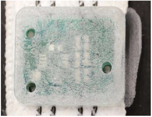
Test series three shows an incomplete filling. The high temperatures cause the material to vulcanize too fast and the packing pressure is insufficient for the complete filling. In this test series, the surface cannot be evaluated with regard to streaks, as the melt front is formed on the surface due to the incomplete filling. A kind of crystal structure is formed Figure 6,7. Figure 6,7
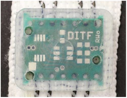
Test series four shows the best results. The sink mark can be reduced by the increased packing pressure without burr formation Figure 8.
Figure 6:Incomplete filling pattern of test series 3 of the full factorial test plan.
Figure 7:Sealing of the cavity by compression of the textile tape (test series 4 from the full factorial test plan).
Figure 8:Reduction of the sink mark caused by a higher packing pressure.
Figure 9:Filling pattern analysis with indication of the metering path.
The surface streaks and the milky appearance of the silicone are eliminated. The minimal scratches on the moulded part are caused by the mould cavity. This is accurately reproduced by the low viscosity of the LSR.
A fill pattern analysis determines without simulation the flow of the melt into the cavity. For this purpose, the cavity is filled under volumetrically and the dosing path is increased to the optimum. The end of the flow path, weld lines and potential air traps can be determined in this way Figure 9.
The filling image analysis, it shows that the melt does not flow evenly around the circuit board and then flow to the ejector side. Instead, the melt passes through the holes in the circuit board. This creates several weld lines in the moulded part. As a rule, weld lines form mechanical weak points in the component. In this application, they do not cause any major problems. In addition, the filling pattern does not remain constant, but varies from shot to shot. The end of the flow path is always in varies places on the ejector side.
Conclusion
The embedding of electronics and textiles in polymer by injection molding has been successful. The process makes it possible to design an automated process with short cycle times. The functionality of the electronics is not affected after the process despite the deformation of the circuit board.
The seal surface around the cavity proves to be very effective. We achieve the sealing effect of the compressed textile. This prevents the formation of burrs to a large extent. The fixing of the circuit board on the positioning pins is also successful. The board is not displaced by the melt front. By minimizing the injection speed and the injection pressure, the deflection can be minimized. The variation of the process parameters shows their effects on the moulded part. A high injection pressure reproduces the part better and the sink mark on the sprue side is significantly smaller. The mechanical stability of the circuit board only permits the use of an injection pressure of 10 bars. By inserting a packing pressure and adjusting a melt cushion, the sink mark is pushed out without increasing the deformation of the circuit board. A fast injection speed results in the formation of air traps below the circuit board. The mould temperature influences the filling, the surface and the cycle time. By increasing the temperature, the material reacts much faster. Thus the cycle time can be reduced. By widening the conductive textile tape, burr formation could be prevented in the long term.
The positioning of the board can be improved to further reduce the deformation of the board. This can be achieved by using a fourth pin. In order to prevent a central deflection, the pins should be positioned close to each other in all four corners. The design of the circuit board and the layout of the traces are a limitation. The boreholes can not be placed anywhere on the board.
Roth K (1996) Konstruieren mit Konstruktionskatalogen. Verbindungen und Verschlüsse, Lösungsfindung: Springer-Verlag. [ Ref ]
Snowden S (2019) This South Korean Team Developed Wearable Technology You Can Put In Your Washing Machine. [ Ref ]
Johannaber F, Michaeli W (2004) Handbuch Spritzgießen. Carl Hanser Verlag GmbH & Co. KG. [ Ref ]
Callegari V (2016) Autoklavierbarer Schutz für Elektronik. Medizin&technik. [ Ref ]
Zwicker T (2012) Mikroverbindungselement für elektrisch-leitfähige textile Strukturen. [ Ref ]
Zwicker T (2012) Mikroverbindungselemente. [ Ref ]
Zwicker T (2013) Kontakt zur Textilen Welt. Kunststoffe. [ Ref ]
Kraus JM (2011) Direktumspritzung zur Einhausung elektronischer Baueinheiten. Maschinenmarkt. [ Ref ]
Kraus J, Kural C (2013) Mediendichtes Umspritzen elektronischer Bauelemente. Maschinenmarkt. [ Ref ]
https://elektronik-umspritzen.de/. [ Ref ]
Haberstroh E, Henze E, Ronnewinkel C (1999) Prozesssichere Verarbeitung von Flüssigsilikonkautschuk (LSR) zu technischen Formteilen. Kunststoffe 89: 68-72. [ Ref ]
Walde H (1996) Beitrag zum vollautomatischen Spritzgießen von Flüssigsilikonkautschuk. [ Ref ]
